
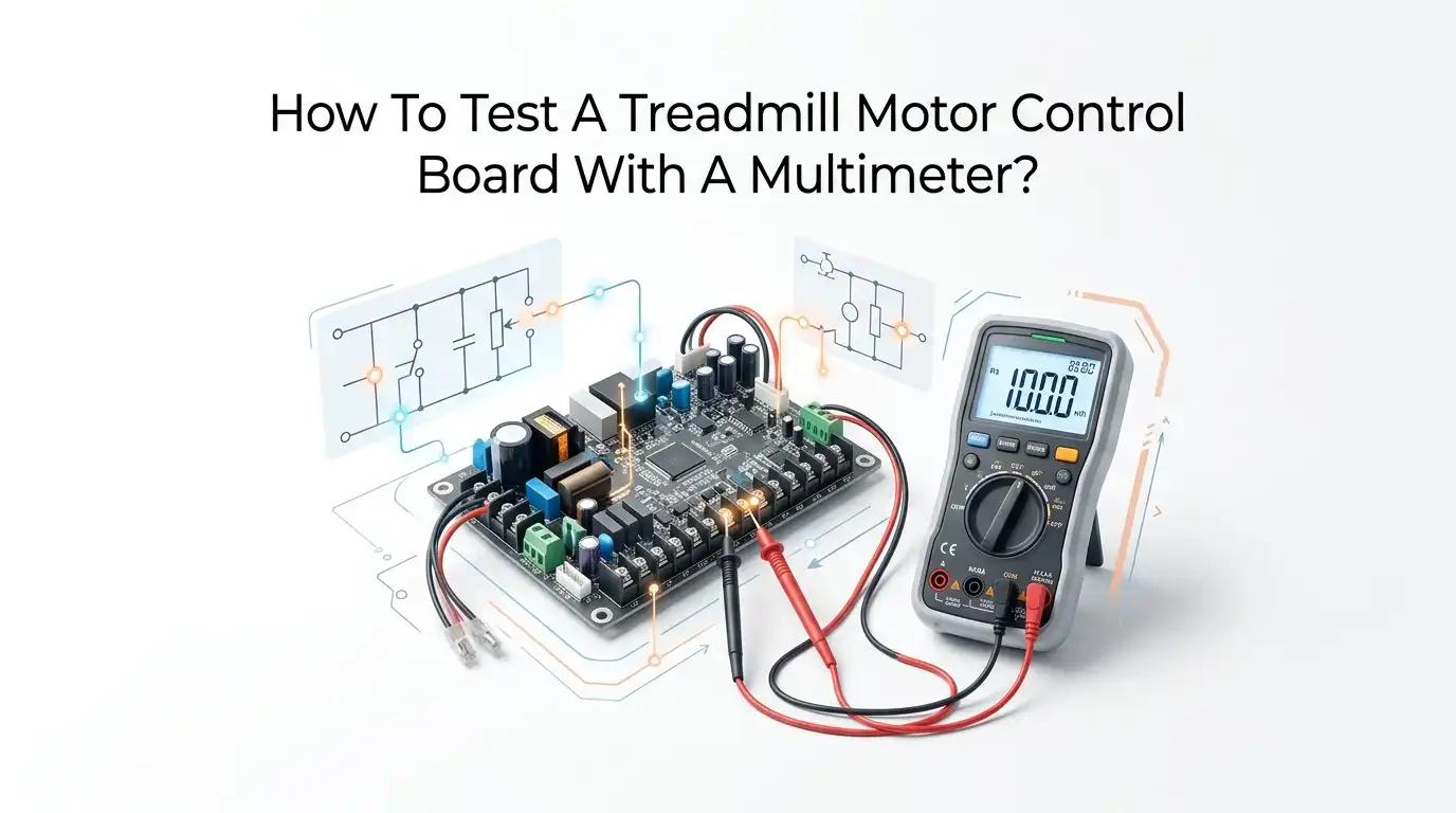
How To Test A Treadmill Motor Control Board With A Multimeter?
Your treadmill suddenly stops working. The belt refuses to move. The console lights up, but nothing happens when you press start. Sound familiar?
In most cases, the motor control board is the part causing all the trouble. This small green circuit board sits under the front hood, and it sends power to the motor. When it fails, your whole machine feels dead.
The good news is that you can test this board yourself. You only need a basic multimeter and a little patience. You do not need to be an electrician to check the main parts.
Key Takeaways
- Safety comes first, always. Unplug the treadmill and discharge the large capacitor before you touch any part of the board. The capacitor can store a dangerous charge even after you pull the plug.
- A multimeter is your main tool. A simple digital multimeter with continuity, resistance, diode, and DC voltage settings is all you need to check most components on the board.
- Start with a visual check. Burnt spots, swollen capacitors, melted parts, and cracked solder joints often reveal the fault before you ever touch a probe.
- Test parts in a clear order. Check the fuse first, then the capacitor, then the diodes and switching parts like IGBTs or MOSFETs, and finally the output voltage to the motor.
- A blown fuse rarely fails alone. If the fuse keeps blowing, a deeper short usually hides in the switching parts. Find the root cause before you replace anything.
- Know when to stop. If the board shows multiple bad parts or hidden shorts, replacement is often cheaper and safer than a long repair.
What A Treadmill Motor Control Board Actually Does
The motor control board, also called the MCB, acts as the brain of your treadmill. It takes power from the wall and turns it into the right kind of power for the drive motor.
The console tells the board how fast you want to go. The board then adjusts the voltage sent to the motor to match that speed.
This board handles a lot of work. It controls speed, manages the incline motor in many models, and protects the system from overload. It also smooths out the power so your run feels steady.
Because it deals with high voltage and heavy current, it carries the most stress of any part. That stress is why the board fails more often than almost anything else. Knowing its job helps you understand why testing it matters so much.
Common Signs Your Motor Control Board Has Failed
Before you grab your multimeter, look for warning signs. These symptoms point straight at a faulty board. The most common sign is a treadmill that powers on but will not move the belt. You press start, the console responds, yet the motor stays silent.
Other clues include a burning smell, a tripped breaker, or a fuse that blows the moment you press start. Some boards cause the belt to surge, jerk, or change speed on its own. You might also see error codes flash on the console.
A motor that runs only at full speed or one stuck at a crawl often means the board cannot control the voltage. Watch for these signs carefully. They tell you the board deserves a closer look and a proper test with your meter.
Safety First: Discharge The Capacitor Before You Begin
This step is the most important one in the whole guide. Skipping it can hurt you. The large cylinder shaped capacitor on the board stores electricity even after you unplug the machine. That stored charge can give you a serious shock if you touch the wrong spot.
Always unplug the treadmill from the wall first. Then wait a few minutes. To discharge the capacitor safely, use a resistor with two probe wires. A 10 ohm resistor works well. Touch one end to each capacitor terminal for several seconds. This drains the charge in a gentle way.
Never short the capacitor with a bare screwdriver. That can cause a spark, damage the board, and send metal flying. Take your time here. Safe work makes the rest of the job stress free.
Tools You Need For This Job
You do not need a full workshop to test a motor control board. A few basic tools get the job done. The star of the show is a digital multimeter. Pick one with continuity, resistance in ohms, a diode test mode, and DC voltage settings. Most affordable meters include all of these.
You will also want a Phillips screwdriver to open the motor hood and remove the board. Keep a 10 ohm resistor with probe wires ready for discharging the capacitor. A flashlight helps you spot burnt areas in dim spots. A small brush clears away dust that can hide damage.
A notepad helps too. Write down each reading as you go. This habit keeps you organized and makes it easy to compare your numbers against the expected values for each part.
Step One: Do A Full Visual Inspection
Your eyes are a powerful diagnostic tool. Many faults show themselves before any meter touches the board. Start by removing the motor hood and taking the board out. Hold it under good light and study both sides.
Look for dark burn marks, brown scorched areas, and melted plastic. Check the large capacitor for bulging tops or leaking fluid. A swollen capacitor is a clear sign of failure. Smell the board too. A sharp burnt odor points to a fried component.
Flip the board over and inspect the solder joints. Cracked or dull joints break the circuit and cause strange faults. Look for any part with a cracked body or split casing. If you find obvious damage, you have likely found your problem. Still, run the meter tests to confirm.
Pros and cons of visual inspection: The big advantage is speed and zero cost. You catch obvious faults fast. The downside is that some failures stay hidden inside parts and leave no visible mark, so you cannot rely on sight alone.
Step Two: Test The Main Fuse For Continuity
The fuse is the first electrical part to check. It protects the board from power surges and shorts. When too much current flows, the fuse blows and breaks the circuit. A blown fuse stops the whole treadmill cold.
Set your multimeter to continuity mode. Touch one probe to each end of the fuse. A good fuse beeps and shows a reading near zero ohms. No beep and an open reading mean the fuse is blown. You can also test it in resistance mode and look for a very low number.
A blown fuse is easy and cheap to replace. But here is the catch. The fuse rarely dies for no reason. If a fresh fuse blows again right away, a deeper short hides somewhere else on the board. Keep testing before you celebrate.
Pros and cons: Testing the fuse is fast and simple. The con is that a good fuse does not clear the board, and a fixed fuse may hide a bigger fault waiting underneath.
Step Three: Check The Main Capacitor With Your Meter
The large capacitor smooths the power on the board. When it fails, the motor runs rough or not at all. You already discharged it during the safety step, so it is safe to test now.
Set your multimeter to the highest resistance range. Place one probe on each capacitor terminal. A healthy capacitor shows the reading climb slowly, then settle high or read open. This means the capacitor charges from the small current in your meter. If the reading stays at zero, the capacitor is shorted and bad.
Compare what you see against a known good part if you can. A capacitor that does not move at all is dead. Also revisit your visual check. A bulging or leaking top confirms the failure without doubt.
Pros and cons: This test catches a major fault that often causes surging or no motion. The limit is that a basic meter only gives a rough idea. A dedicated capacitance meter gives a far more exact number.
Step Four: Test The Diodes Using Diode Mode
Diodes guide current in one direction. When they short or open, the board cannot manage power correctly. Your multimeter has a special diode mode marked with a small diode symbol. Switch to it for this test.
Place the red probe on one side of the diode and the black probe on the other. A good diode shows a reading around 0.4 to 0.7 volts in one direction. Then swap the probes. In the reverse direction, a healthy diode reads open or OL.
A diode that beeps or reads near zero in both directions is shorted. A diode that reads open both ways is broken. Either result means you found a faulty part. Test each diode you can reach, since one bad diode often signals more damage nearby.
Pros and cons: Diode testing is precise and clear. The downside is that some diodes sit close to other parts that can affect the reading, so you may need to lift a leg for a clean result.
Step Five: Test The IGBTs Or MOSFETs
The IGBTs or MOSFETs are the switching parts that drive the motor. They handle heavy current, so they fail often. These parts have three legs. You can test them in diode mode much like a regular diode.
Place your probes across the collector and emitter pins. A healthy part shows a forward drop near 0.5 volts in one direction and open in the other. A reading of zero volts means the part is shorted and dead. A reading of open in both directions can mean it failed open.
Shorted switching parts are the usual reason a fuse keeps blowing. When the IGBT shorts, it pulls huge current and pops the fuse instantly. So if your fuse blows again and again, check these parts first. They sit on a metal heat sink and are easy to spot.
Pros and cons: This test finds the most common deep fault on the board. The con is that in circuit testing can give false results, so removing the part gives the most reliable answer.
Step Six: Measure The DC Output Voltage To The Motor
This test checks if the board sends proper power to the motor. You do this with the treadmill plugged in, so work with great care. Set your multimeter to DC voltage on a high range, such as 200 volts or more.
Touch the probes to the two motor output terminals on the board. Press start and slowly raise the speed on the console. A working board shows the voltage rise smoothly as speed increases. Low speed gives a low reading, and high speed gives a higher one.
A reading that jumps around wildly points to a faulty board. For example, voltage that swings between 10, 80, and 20 volts in seconds shows the board cannot hold a steady output. No voltage at all, even with the motor commanded to run, confirms the board fails to deliver power.
Pros and cons: This live test shows real performance under load. The clear downside is the shock risk, so keep hands clear and probe with steady care.
Step Seven: Test The Power Supply Input
The board needs clean input power to work. If the input is wrong, the board cannot do its job. This test checks the power coming into the board from the wall and the on off switch.
With the treadmill plugged in, set your meter to AC voltage. Measure across the input terminals where the power cord feeds the board. You should see a steady reading near your wall voltage. A reading far below normal points to a bad cord, switch, or wiring fault before the board.
Do not blame the board if the input power is missing. Many people replace a good board when the real fault sits in the power switch or a loose wire. Always confirm the board receives proper power first. This simple check saves money and time.
Pros and cons: The test rules out simple upstream faults fast. The con is that it does not test the board itself, only what reaches it, so you still need the other steps.
How To Tell If The Board Or The Motor Is Faulty
Sometimes the motor is the real culprit, not the board. You can test the motor on its own to be sure. First, disconnect the motor from the board. Set your meter to resistance mode and measure across the two motor wires.
A good motor shows a low resistance reading, often a few ohms. An open reading means a broken winding inside the motor. You can also spin the motor by hand and watch for a small voltage on your meter, which shows the motor generates power and works.
To test the motor under power, apply a low DC voltage to its leads. A healthy motor spins right away. If the motor runs fine with direct power but not through the board, the board is the problem. This simple split test points you to the true fault.
Pros and cons: This method clearly separates board faults from motor faults. The downside is that applying direct power needs a safe DC source and careful handling to avoid a sudden jolt.
When To Repair The Board And When To Replace It
After all your tests, you face a choice. Should you fix the board or swap it for a new one? The answer depends on what you found. A single blown fuse or one bad diode is an easy and cheap fix worth doing.
A board with several burnt parts or hidden shorts is often not worth the effort. Chasing many faults takes time, and you may still miss one. In that case, a new or refurbished board gives a more reliable result.
Think about your own skill level too. Soldering small parts takes practice. If you feel unsure, replacing the whole board is the safer path. Also weigh the cost. When repair parts and your time add up close to a new board price, replacement makes more sense. Trust your test results to guide this call.
Frequently Asked Questions
Can I test a treadmill motor control board without removing it?
Yes, you can do some tests in place, such as the fuse check and the DC output voltage test. Still, removing the board gives better access. It lets you inspect both sides and test switching parts without nearby components skewing your readings. For a full and accurate check, take the board out.
How do I know if the capacitor on my board is bad?
Look for a bulging or leaking top first, since these signs confirm failure on sight. Then test it with your meter on the resistance range. A good capacitor makes the reading climb slowly and settle high. A reading stuck at zero means the capacitor is shorted and needs replacement.
Why does my treadmill fuse keep blowing after I replace it?
A fuse that blows again points to a deeper short on the board. The most common cause is a shorted IGBT or MOSFET. These switching parts pull massive current when they fail and pop the fuse at once. Test those parts in diode mode before you fit another fuse.
Is it safe to test the board while the treadmill is plugged in?
Only certain tests need power, like the DC output and input voltage checks. Treat these with great care. Keep your hands away from high voltage spots and use steady probe contact. For all other tests, unplug the machine and discharge the capacitor first to stay safe.
What multimeter settings do I need to test the board?
You need four main settings for a complete check. These are continuity, resistance in ohms, diode mode, and DC voltage. Continuity tests the fuse, resistance checks the capacitor and motor, diode mode tests diodes and switching parts, and DC voltage measures the output to the motor.
Can a bad motor control board damage my treadmill motor?
A failing board usually will not destroy a healthy motor, but it can stress it with poor power. Surging or uneven voltage makes the motor run rough. Over time, that strain can wear the motor faster. Fixing the board promptly protects the motor and keeps your treadmill running smoothly.

Hi, I’m Sarah Hill — the founder and voice behind Heavy Lift Vault. I’m passionate about fitness, strength training, and health technology. I spend my time researching, testing, and reviewing workout equipment and health devices so you don’t have to guess. My goal is to deliver honest, detailed, and trustworthy reviews that help you invest wisely in your fitness journey.